System Design Overview
All of the robots that I have programmed follow the same general structure.
Most importantly, an output (in our case a single motor) should only be controlled by one subsystem.
Additionally, each output should be set on every iteration - in the case of a motor, that means that it should have .set() called each iteration even if our demand is the same.
The robot code is designed to be flexible and modular.
In other words, I want to it be as easy as possible to add new features without too much refactoring.
So as an example, if the current featureset was all that this robot will ever do, there's no good reason for Accelerator or Rollers or Indexer to exist.
The ease of adding functionality in the future outweighs the extra code (commonly referred in software as Boilerplate).
They also add consistency as all of the subsystems are structured in the same way.
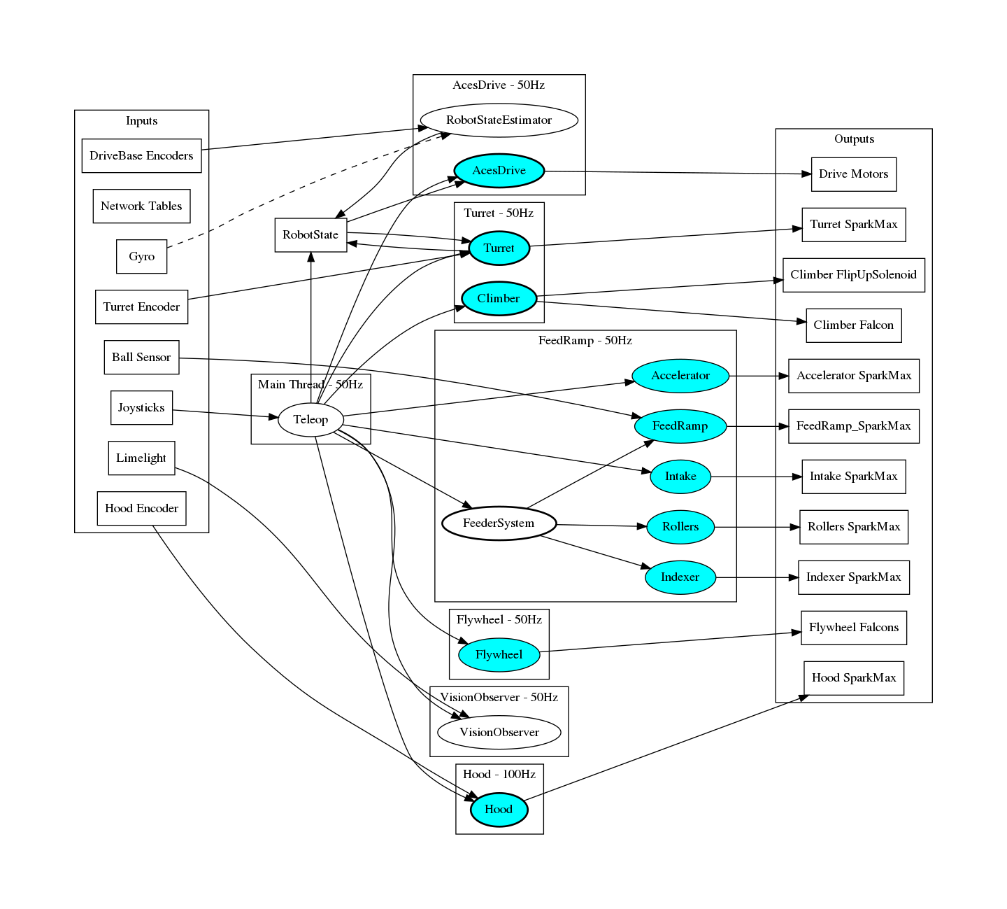
Each circle in the middle is more/less a "logic unit". That is to mean that on each tick/loop/iteration it takes some inputs, does some logic, and writes outputs.
Each blue shaded circle extends AcesSubsystem.
All this means is that it loops at a certain period, holds and outputs telemetry, and can supply faults.
FeederSystem, for example, only implements Loopable and TelemetryProvider<> because it doesn't really "fault".
Though I think this was more of chance as I could've just implemented AcesSubsystem and left checkForFaults() empty.
RobotState is not a "logic unit" as it only holds data, but I felt that it's important enough in order to show the flow of data through the control system.
Bolded circles indicate there's notable extra logic (state machines or alike) going on inside of them.
The dotted line from Gyro to RobotStateEstimator is to denote that although Gyro is in AcesDrive, the only place that it's really used is RobotStateEstimator.
Any piece of code that wants to use this information uses RobotState.getLatestFieldToVehicle().getValue().getRotation() or alike.
Threads
Rationale
The main reason why the software has multiple threads is decoupling and convenience.
It's very easy for me to make the Turret iterate faster or slower, or if I want to see what happens with path following if I crank AcesDrive to to 200Hz.
Another reason is separating deterministic code from nondeterministic code. Some calls have a timeout and you don't want those stacking up if there's a motor disconnect. Setting a motor's neutral-mode is an example of this
Core threads
- Main Thread
This thread is what calls
teleopInit()/teleopPeriodic(),autonomousInit()/autonomousPeriodic()androbotPeriodic()inRobot. This is all managed by WPILib.
Every other thread uses the Looper construct. In particular I use InterruptLoopers. Loopers are explained here)
-
AcesDrive
Manages the drive base/path following/ground pose estimation
-
Turret
Controls the turret. Includes the climber as climber-turret interlocking may have been needed
-
FeedRamp
"Main subsystem thread" more or less. It's where everything else went.
-
Flywheel
Wasn't sure if we needed the flexibility of running this at a higher rate. During development, I increased this to 100 or 200Hz to give us better current draw resolution.
-
VisionObserver
Remove jitter from Network Table calls from the rest of the system (just in case)
-
Hood
Runs at a higher rate to allow it to properly fuse the CanCoder and the Neo550's motion magic control loop
Honorable Mentions
- RioToCoDataStreamerSender
- DataStreamerDataSender
- AutoSelectionManager
- DataStreamer/ExternalActions
- Lights (had they been added)
- LifetimeStatistics - .5 Hz
- FaultChecker - 1Hz
Each logic unit
AcesDriveRuns paths/sets drive base outputsTurretAim at targetClimberFlip up state machineFeederSystemBall detection/queueing logicHoodCanCoder/SparkMax encoder fusionFlywheelis not bolded as an example because the only logic is to count the number of balls shot.